The History of Duigan Flights (cont)
The first sketches Uncle Jack made showed the same general layout, but with a number of differences. There was to be a biplane tail with a very large rudder hinged at the leading edge. The rear booms had a curved top cord which was evidently distorted to take the upper tail plane. This was worked over on the drawing and reduced to the simple triangle of the final design. I think the upper tail pane disappeared at this time. The sketch shows two front wheels and a tail wheel of the same size, so the machine was to be in the flying attitude all the time, like a reversed tricycle. The front elevator was to be very large and carried about half the length of the aircraft, in front of the centre of gravity. So Uncle Jack, evidently, felt very sensitive about fore and aft control and had no intention of getting into an uncontrollable dive. For lateral control the two outer bays of each main plane were given a marked dihedral; the inventor evidently understood that this worked through side slip, since there was never any suggestion of side curtains a la Voisin. The way in which lateral control was to be exercised was evidently thrust. If, say, the left wing dropped you ruddered to the right and the skid against the dihedral, as well as the increased speed of the wing, picked it up. With this system it would be impossible, one would think, to do other than a banked turn.
Anyway, this was never really put to the test, because in the first version as built, the dihedral was reinforced by the addition of small controllable balancing planes between the wingtips. This change from the original design suggests very strongly to me that Uncle Jack, without flying at all, had solved the problems of control in a very simple way by saying something like this. The aircraft can be displaced from its designed attitude by rotating about all, or any. of the three mutually perpendicular axes through its centre of gravity. That is, the fore and aft, the athawartships, and the vertical. Let us then add voluntary control that acts about each of these axes. There’s more to it than this, of course, but the principal seems so obvious that its hard for us to realize, at the time, most of the aircraft in Europe only had two sets of controls, and that even the Wright’s came about the third, [ the rudder], in a very roundabout way.
Now comes a rather an odd thing. The original layout shows an equal angle of attack for tail and main planes, and the centre of gravity would evidently fall appropriately between them, so the lifting moments balanced. In other words, it was really a tandem aeroplane. Then the upper tail plane disappears from the back and reappears immediately behind the front elevator and the machine was built in this way. This suggests that a better determination of the centre of gravity [possibly made during production] indicated that even without the second plane the tail would out lift the main plane, so a lifting plane forward was introduced to offset this effect. At the same time it suggests that the concept of automatic fore and aft stability, resulting from a non lifting tail plane was not understood, which doesn’t square with Father’s model. The most likely explanation is that the idea was understood but discarded in favour of voluntary control and maximum lift.
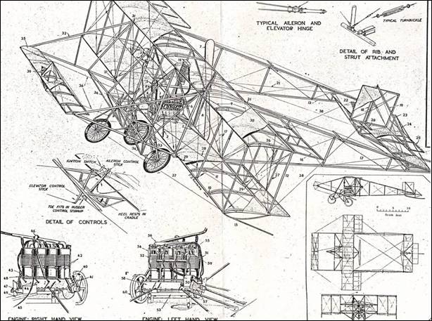
Although this does not appear at first glance, modern production methods were anticipated, in that, the three inner bays of the main planes were constructed as a unit, with the undercarriage, engine mounting and the fore and aft booms. The two outer bays at the end of each wing were made up independently, so they could be removed or altered without dismantling the whole plane.
Uncle Jack was not a civil engineer, but he seems to have shown a complete regard for the principles of framed structures, space frames at that, not just two dimensional trusses. I’ve had a pretty good look over the machine from time to time and I’m sure there isn’t a redundant member in it, nor are any essential ones missing. Most of the European designs of the time exhibit numerous anomalies, the usual being square section compression members carefully braced in one plane and left swinging in the other.
Referring back a moment, to the drawing in the previous photos, this shows the final airworthy design. A tail skid has taken the place of the tail wheel; the undercarriage appears to be a tricycle, but the front wheel is only an anti tipper-upper. The front plane has gone, and so have the mid plane ailerons, these being replaced by large trailing flap types, A tiny fin has been added to the front elevator and the true trailing flap elevated to the rear plane.
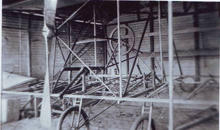
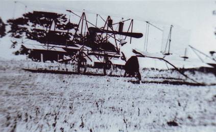
This picture shows the machine in the first state, and well on the way to completion,. The time would be mid 1909.
The main spars and struts are of mountain ash, air dried in those days, the formers, red pine and the engine frame and undercarriage mountings, steel tubes, and the rest piano wire.
The main components of the undercarriage legs that are prominent here, were made in Melbourne by Brown Brothers, who did a steady trade in motor bikes for Duigan Brothers. Although Father’s memory of this period is weak, he recalls that Mr. Brown had a wicked gleam in his eye, which seems to mark him out as the ancestor of all motorbike traders.
The forks were pneumatic, with rubber cup pistons, lubricated with glycerine. Before a days flying they were pumped up to 100 p.s.i., and in their final form they held their pressure for weeks at a time. In this picture they are mounted to only swing along a fore – and - aft line, but in the authorized version they were mounted on gimbals that permitted a fair degree of swivel, to take up drift on take off or landing. This all seems a rather elaborate answer to a problem that on first sight does not seem to exist, since there was no intention of flying in strong cross winds. On second thoughts the absence of fuselage would mean that the plane would yaw easily and with nothing much to sight on in front, there would be a tendency to fly crab-like, anyway. Add to this that the banked turn was unknown, so the pilot would be ruddering into the drift and therefore skidding like mad and the swivelling undercarriage instead of being a luxury, becomes a necessity.
The wheels had a swiveling linkage, so with the trial of the forks they castored when the weight came on them and never tended to shimmy.
The propeller shown here was built up in spruce by a firm of pattern makers whose name may have been Moore, to figures derived by Uncle from as expected, air speed and power output. The extended hub looks as though it would have weakened the blades but they stood up alright. Uncle apparently had a lively apprehension of where they would go if they broke off, [forward through the pilot]. We’re looking from the back, because you can see that the shaft was extended, and the tips were braced back to it.
Although this propeller looks adequate, it was eventually replaced by one which differed largely, in that, Uncle Jack removed most of the wood from it, and I think it was slightly larger, 8 ft 6 ins, and the pitch slightly steeper, 10 ft. Both propellers were covered with linen.
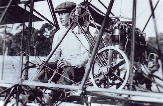
The wire wheel at the back is a large V pulley about on 1½” x 7/8” deep. As the engine power was gradually increased, this system of belt drive became progressively more unsatisfactory and was eventually changed to chain and sprocket. The final drive ratio was 19/42.
This picture shows the original leading fixed plane already covered, and the front elevator likewise. The fabric was a rubberized cloth which we think was balloon cloth. Joins were made by adding a reinforcing strip, and sticking the lot together with rubber solution, a large tin of which can be seen on the flight deck. Ring side members of the audience will be able to read the brand – ‘Dunlop Solution.’
Now almost the final item before we take to the air.
No suitable light weight engines were available in Australia, so Uncle collaborated with a friend of his, J. E. Tilley, who had an engineering works in Melbourne. On the production of a four cylinder in line, air cooled motor, 86 mm bore x 108 mm stroke, which is about 2.5 litres, This was reputed to give 20 h.p., but Father can’t remember any tests of this, or of the thrust from the propeller, being made. Although he feels it was unlike Uncle Jack not to get the power produced to figures.
The airframe was certainly tested by setting it up on trestles and loading it with sand bags. It was apparently ready before the engine, so when the latter arrived, obviously, the best way to test it was to take it for a drive.
The cylinders were separate barrels with roughly the middle third finned. Valves were on top of the heads with exhaust on one side, and inlet on the other, with the plug mid way, they operated by long curly push rods from separate cam shafts on either side of the engine.
The flywheel had blade shaped spokes, a refinement to help the cooling. It was one of the heavy components of the engine, but as far as I can find out, it never occurred to anyone to try with the propeller only as a flywheel.
An example of good engineering practice was the adjustable spreader carried on roller bearings on the flywheel and propeller shaft which tensions, the chain without loading the crankshaft bearings. This derived from the original belt drive where the belt finally finished up like a fiddle sting, but was still slipping. An example of bad industrial practice was the lack of a chain guard of any shape or form; and an example of bad airmanship was the absence of a safety belt or harness.
The engine weighed about 135 pounds complete and if in the end it was really delivering 25 hp it was about on a par with most of the specially developed engines in Europe, which seems to have varied between 5 and 8 pounds per horsepower. Although the recognized ones were more reliable, and had the cooling problem well under control in a cooler climate. The R.E.P and the Gnome were just beginning to appear about this time, and the big reduction in the amount of crankcase and crankshaft for radial and rotary, put them ahead of the field, until speeds got up enough for frontal areas to have some significance.
We have a photo of Father carrying the complete engine up from the creek after a mishap. So the weight must have been somewhere about that given.
While I have this picture on I’d better go through the main modifications that were made to the engine which were found to be necessary. First a new set of larger cylinders, 94 by 108 mm, and Uncle made a hand boring rig to fit these to the crankcase. Later the compression was raised by riveting 3/8ths aluminum plates to the top of the pistons. We have an account in a letter of the compressions being measured by filling one cylinder with oil, with the piston up, and then down, but tantalizing, the actual compression result is not given.
The value area was evidently a bit small, because steadily improved results were obtained by progressively reducing the engine speed by changing the drive ratio. Starting at 14/42, it eventually finished up at 19/42. Maximum power probably dropped slightly but the cooling would be improved. Arising from the limited size of the exhaust valves was the installation of auxiliary exhaust ports, in the fashion of a two stroke. This device was one of Uncle Jack’s favorites and sprang from motorbike practice. Both he and Father were in the habit of competing in 100 mile road races in Melbourne and at one time had identical machines, 4 cylinder FN’s. So with one for the control rhea had a good opportunity of testing the efficacy of modifications like this. You can see a port quite clearly just to the right of the first curly push rod.
In due course, however, heavier valve springs were fitted, and the valves and ignition timing were no doubt juggled around ad nauseum. The ignition system which remained unchanged throughout, comprised, a single cylinder motorbike magneto, run at twice engine speed, connected to a 4 cylinder FN distributor.
The original carburetor was too restricted in the throat and was replaced by a motor buggy one. The final big change was the fitting of water cooled heads, a radiator and a water pump. Uncle Jack made the radiator forming flat tubes out of sheet brass and fining them to produce a total area of 13 sq feet. A laborious job which he describes with some pride in a letter to the editor of the Aero. He also made the pattern for the water pumps, which had a centrifugal impeller and was about the size and type of the present day motor car type. A number of European engines of the time were still using thermo- siphon].
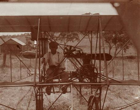
The control wires from the rudder were brought across in front of the pilot parallel to the main plane, then round pulleys and back to a horn on either side of the rudder. Although its hard to imagine any other way of operating than by a rudder bar, Uncle Jack, for once, avoided the combination of the obvious and the logical and instead provided a loop, into which one foot was thrust and waved in the direction in which it was desired to travel You can’t quite see it, but it is there into which one foot is thrust and waved in the direction of which it is desired to travel. When I say that the conventional rudder bar is obvious, don’t forget the Wright’s had their rudder connected to the stick, [the wing warping stick], so that a forward movement ruddered to the left and backward to the right; and the elevators were controlled by a separate stick, but the same movement. The Duigan had a conventional stick moving sideways to operate the ailerons, and as only the working ones were pulled down, you can see, that, if you were picking up the right wing, the left wing slack must have just about been rubbing on the flywheel.
The fore and aft elevators operated together from a separate stick which had a rather rough hewn handle, visible beside the pilots right hand.
Unlike the Wright, which ran full bore or nothing, and had a valve lifter to stop it, the Duigan was thoroughly domesticated with a throttle and ignition switch. Because both hands were occupied with sticks, the ignition switch took the form of a cut out button mounted on the aileron control, and descent was affected by flipping the engine like the war time gnomes. Although it was pretty rough, the engine would throttle down to allow the aircraft to remain stationary, or at least to advance only at walking pace.
So much for the controls, now the instruments, there were no instruments. That pretty well covers the aeroplane.
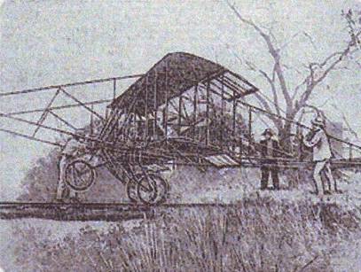
The Aerodrome – plane being taken over creek
Plane on flat ground below slope
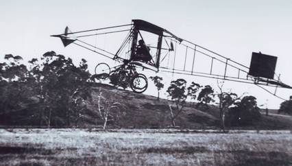
Lateral view of plane flying over ‘ Aerodrome.’
The aerodrome was about 1300 yards long, the south end only about 200 or 300 yards from the homestead, but down quite a steep hill on the other side of the creek. Pohlman’s Creek by name, it was just big enough to have a name. It was a good creek flat, and had naturally been a cultivation paddock. At the time of the aeroplane, it had been sown down a few years, and the furrows had almost gone, but the lanes [at right angles to the take off or landing] were still quite deep, and gave the undercarriage a thorough testing which it stood up to perfectly, on and off for a year.
The field ran more or less north south, with the creek on the west, and the steep timbered hills on the east. It was never more than a hundred yards wide and had a pretty solid bend in the middle about 135o.
The primeval plane was first tested early in 1910. If it had then flown, like it finally did, it would have won the 5,000 pound prize for ‘aerial invention,’ which the Aerial League of Australia [newly formed in 1909] had needled the Federal Government into offering in September of that year. This prize was, of course, in no way the incentive that started Uncle Jack off. The aircraft was nearly finished when it was offered.
About the time the Duigan first emerged from its hangar, Australia was invaded by a number of imported primitive aircraft among them a Wright, a Voisin and a Bleriot and claims and counter claims about those, apparently led to the prize being eventually withdrawn.
Plane down on one wing
So far from winning a prize, the first test on the Duigan was a total failure. The machine taxied forward briskly enough, but failed completely to rise. During each attempt the engine quickly overheated and lost power. After some days of this, in an attempt to gauge how much additional power was necessary, the machine was pushed up the side of one of the small hills and launched down it at a small bump out on the flat. When it reached this, it leapt into the air and despite Uncle Jack’s best efforts on the elevator, [only the front one was fitted at this stage] the angle of climb instantly steepened to about 45 degrees and the aircraft stalled and fell to the ground on one wing.
No great damage was done to the main frame but it was back to the old drawing board in a big way for all that. At the time, the leap was attributed to the front fixed plane, and it was forthwith abandoned and the balancing of the various lifting components from then on was done by trial and error.
I don’t know whether the precise sequence of events producing the uncontrollable leap was ever elucidated in detail, but it is probably something like this.
Main planes, and back and front planes were all rigged at the same angle of attack and on paper, the moment of the tail plane, [combined with the small couple, due to the centre of thrust being slightly higher than the centre of drag], should have, if anything, exceeded the moment of the front plane about the centre of gravity, [which was roughly the centre of pressure of the main planes]; or stated more succinctly, the sum of the moments should have been about zero with the front elevator to make up the difference.
In practice the tail plane would be in the down wash from the upper wing and may have even had a negative angle to the relative air movement. [Although the effect would not have been pronounced until it got a few feet in the air]. This would initiate the nose up movement. The front elevator would, of course, have been instantly rotated, but since it was below and in front of the fixed plane, the effect would be to increase the angle of the relative wind to it, and hence its lift.
Anyway the front plane was abolished, and as there still appeared to be ample lift forward of the centre of gravity. The front booms were reduced in length by one bay, reducing the total length of the aircraft from 35 feet to 29 feet. This turned out, at first sight, to be a false move, because the elevator moment arm was now too short for effective control. Rather than retrace his steps, Uncle Jack fitted a controllable flap to the tail plane where there was plenty of leverage and thus with no more than a few bounces in the air to furnish data, evolved what was to become the accepted stable tail for all future aircraft, starting from the original Wright type of unstable layout. While the Wrights, themselves, still persisted with it after four or five years experience.
{To digress for a moment, after Wilbur’s European season, they were no doubt well aware of the system’s defects, but could not admit them, because of the Patent infringement cases in preparation.]
Eventually the new cylinders and larger propellers were fitted and testing started again. By July 16th 1910 the machine was indubitably flying, rather then bouncing, but the belt drive not transmitting the whole of the increased torque, and even if it had been, the engine was still overheating. The change to chain drive then followed and the positive drive and the increased action of the bigger propeller promptly wound up the propeller shaft. A heavier one was fitted, and the aircraft flew well, but the engine still overheated. If it would have been possible to carry out sustained flying after takeoff, this characteristic would not have been so pronounced, but this was impossible due to the nature of the surrounding country. This was more or less the luck of the draw because Grandfather Duigan, while not exactly a speculator in stations, had owned quite a few before Spring Plains. He had owned properties around Cobar which ran to about as many square miles as Spring Plains did acres and where there were no obstructions to speak of like trees or hills or even grass.
Anyway the change to water cooling was imperative. It was made and the machine was an aeroplane.
Still not in the air yet. This shows the machine returning to the hangar after a morning’s flying; up the rather steep pinch from the creek to the homestead. It weighed over 500 lbs empty, and three men could just get it up the hill. That would be Father, straining at the tail plane. The likeness is not good, but he still wears the same hat.
John Duigan at controls
John Duigan at controls

